How to reset Tuya's Bluetooth module and configure the network?
When receiving the module, it is suggested that, before start coding, you run the provided module debugging assistant to check if the module can work properly. In MCU simulation mode, connect the module and configure the network for practice. Meanwhile, you can get familiar with the protocol interaction process, which will help you to proceed with the development debugging.
Tuya BLE general serial port protocol architecture is as follows:
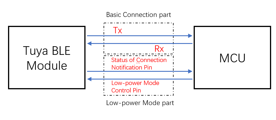
- Low power mode control pin: currently, for general connection solution to door locks (use TYBN1 module and BK3431Q chip), it is the required control pin in coordination with MCU connection. For more information, see Tuya Universal Serial Port Protocol. For other general connection solutions, if the low power function is not used, TX and RX pins can complete the basic protocol interaction. If the low power function is used, you must connect the low power mode control pin of the module.
- Status of connection notification pin: in low power mode, when mobile phone Bluetooth is connected, the GPIO outputs high electrical level. When it is disconnected, the GPIO outputs low electrical level.Note: certain modules do not support this function. For more information, see Tuya Universal Serial Port Protocol. (Optional, silk screen varies by pin models, see datasheet for more details)
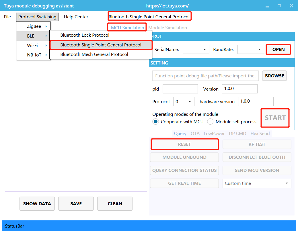
In MCU simulation mode, the debugging assistant simulates the MCU to automatically respond to the module with the correct protocol data. After you configure network through the mobile phone, you can test DP data reporting and sending. The procedure of operating the assistant and module network configuration is as follows. Before operation, you need to learn about the operation instruction of Tuya module debugging assistant. For beginners, you can refer to Module Debugging Assistant Instruction.
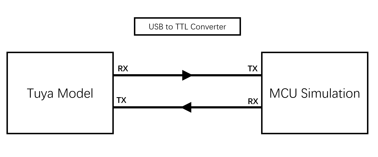
The connection diagram in MCU simulation mode of the debugging assistant is as follows:
- Based on the schematic diagram of the minimum system, you build the peripheral circuit of the module, and jump the wire directly in case of simple testing.
- Open the debugging assistant in the development documents, and import the debugging file. Choose BLE &rt; Bluetooth Single Point General Protocol, and MCU Simulation.
- Connect the module serial port to the computer through USB-to-TTL adapter, and select the corresponding serial port and Baud in the assistant. After you open the serial port and click Start, you will see the initial protocol interaction between the module and the host.Note: BLE module will constantly send heartbeat packets after power-on. When receiving the correct response, it will proceed with the initial protocol interaction. If the module does not send data after power-on, check if the peripheral circuit of the module is correct.
- Click Reset, and the module Bluetooth will be disconnected. Unpair Bluetooth connection, clear offline cache information of the module, and then reboot.